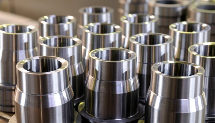
The Importance of Tool Holder Care and Maintenance

Tool Holder Care and MaintenanceTool holder care and maintenance is of vital importance (especially when working with CNC machines) for many reasons!

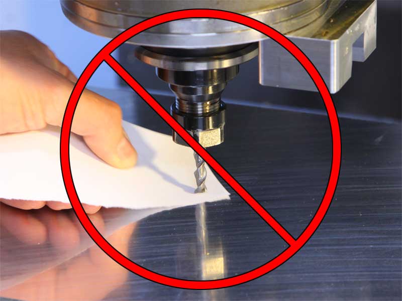
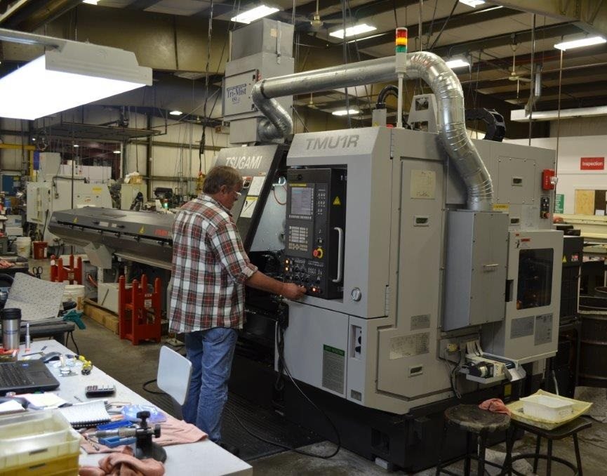
A rule of thumb to live by when working with CNC Machines is that an inspection of the toolholder and spindle should follow every use.

This inspection should include disassembling the entirety of the toolholder and cleaning the parts.

The coolants used while operating the machine can leave residue on the toolholder parts, which can lead to serious adverse effects.

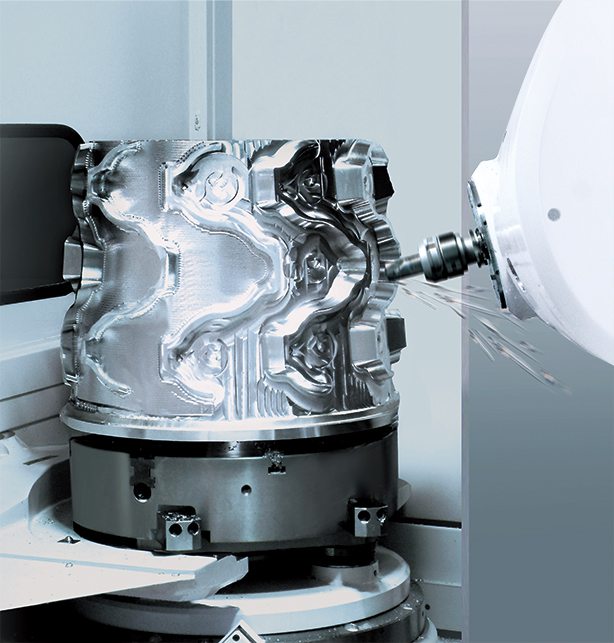
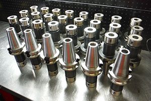
Adverse Effects Tool Holders for CNC Machines

CNC machine tool holder care and maintenanceAn example of a detrimental effect is a small chip left in the coolant. This chip can degrade the tool’s performance by scratching or scraping the parts.

In turn, this will cost more money for the shop as they will need to replace the parts of their toolholders quicker than they should have to, and potentially ruin the job they are working on.

An even worse possibility is an accident with the machine and the operator being injured. For these reasons, it is imperative that after operation of the machine, the toolholder is dismantled, cleaned and inspected to ensure it is free of any contamination.

The spindle should also be checked and maintained to ensure it is working to its full potential. Periodically throughout the year a ForceCheck Guage should be employed to test the pulling power of the spindle on the machine.

A record of the results should be kept regularly and when a disparity occurs it must not be ignored. A decrease in pulling power can be a warning sign of problems within the machine and if left unchecked can result in a damaging accident for the operator.

CNC Machines: Tool Holder Care and Maintenance, Bottom Line

Taking the time to inspect and clean all parts of the toolholder and spindle can reduce potential costs for a shop over the lifetime of the machine. It can create a safe and hazard free working environment while diminishing the chances of an accident.

Source:

http://www.productionmachining.com/articles/8-easy-tips-for-spindle-and-toolholder-hygiene

What Are CNC Offsets?

Every practice of compensation has to do with offsets (especially in regards to CNC offsets)!

One can consider CNC offsets as memories on an electronic calculator. If your calculator has memory, you can store a constant value to each memory for use throughout a calculation. This keeps one from having to enter the number over and over again.

Like the memory of an electronic calculator, offsets in the CNC control are stored locations into which mathematical values can be entered. Just as the value in the memory of a calculator has no sense until referenced by its operator in a calculation, the value contained by an offset of the CNC regulator does not have any significance until it is referenced by a CNC program.

From the marksman analogy, one can think of the values deposited in CNC offsets as the sum of modification necessary on the prospect of the search needed to compensate for detachment to the aim. Remember that the rifle only requires alteration for one resolution, to modify for the detachment to the aim. With most CNC machine tools, it is necessary to have at least one offset for each tool.

Read more about your machines at our blog here.

Causes of tool offsets
kakouB2_1
Offsets can be recycled for numerous determinations dependent on the style of device tool and sort of compensation being used. Here are some of the more collective presentations for offsets.

For machining midpoint applications, it would be very problematic for the programmer to forecast the exact length of every tool used in the program.

To this end, the feature tool length compensation trusts the programmer to check every tool’s length as the program is written. During the setup, the programmer measures the length of each tool and inputs the tool length value into the equivalent offset.

While milling on the edge of the cutter (contour milling), it can problematic for the programmer to program the cutter’s track founded on the size of the milling cutter being used. Similarly, if the cutter size must modify (possibly due to re-sharpening), it would be impractical to modify the program based on the fresh cutter size.

For this reason, the feature cutter radius compensation lets the program writer override the cutter size as the program is inscribed. The operator inputs the size of each milling cutter into its corresponding tool offset. In the same manner, rotating centers have a feature named tool nose radius compensation. With this feature, an offset is used to identify the radius of the very tip of the turning or boring tool.

Machining centers that have match offsets (also called coordinate system shifting) let the worker identify the location of the program zero point within offsets, keeping the assignment of program zero separate from the program. In the same way, many rotating centers allow the assignment of program zero via offsets (this feature is usually named geometry offsets).

Tool offsets are used on all turning centers to let the worker grip size with tools used in their programs. This permits the worker to regulate for flaws with tool settlement during setup. It also permits the worker to regulate the tool’s movements to permit for wear throughout every tool’s lifespan.

Ref: CNCCI

Understanding Absolute Mode (G90) Vs Incremental Motion: CNC Machines

Incremental system. Absolute system. Most controls on machine tools capable of handling both by altering code between G90 (absolute) and G91 (incremental) commands.

All considerations to this point accept that the absolute mode of programming is used. The CNC word used to refer to the absolute mode is G90.

In absolute mode, the end points intended for all motions will be identified from the program zero point. For beginners, this is typically the best and least complex method of identifying end points for motion commands. However, there are alternative methods of stating end points for axis motion.

Dont know about motion? Read our article here.

In incremental mode (generally stated by G91), end points for motion are identified from the tool’s present position, not from program zero. With this technique of imposing motion, the programmer must always be asking “How far must I transfer the device?”

While there are still periods when the incremental mode can be helpful, generally speaking this is the clumsier way of stating motion and learners should focus on using absolute mode.

imgtfcvhages
Be cautious while building motion commands. Learners have the tendency to consider incrementally. If functioning in the absolute mode (as learners should), the programmer should constantly be questioning “To what circumstances must the device be moved?” This condition is comparative to program zero, NOT from the apparatus’s existing position.

Apart from making it very simple to decide the present point for one command, another advantage of functioning in absolute mode has to do with errors made over the course of motion commands.

In absolute mode, if a motion error is made in one command of the program, simply one movement will be inappropriate. On the contrary, if an error is made in the course of incremental movements, all motions from the point of the error will also be inappropriate.

Allocating Program Zero (Absolute Mode)

Remember that the CNC control must state the site of the program zero point by one means or another. How this is completed differs widely from one CNC machine and control to another. An (older) technique is to consign program zero in the program.

With this technique, the programmer tells the control how far it is from the program zero point to the preliminary point of the machine. This is usually completed with a G92 (or G50) command at least at the starting of the program and perhaps at the beginning of every device.

A different, fresher and improved way to allot program zero is to use some form of offset. Normally, machining midpoint control producers call offsets used to allocate program zero fixture offsets. Turning center manufacturers usually call offsets used to consign program zero for every tool geometry offsets. Further on how program zero can be allocated will be accessible through theory number four.

Ref: cncci.com

CNC Cutting Tools: Categories and Features

CNC cutting tools can be divided into two main groups: traditional tools and modular tools. Modular tools are the tools of progress.

The chief benefits of modular tools include reducing tool modification downtime, developing production and processing time, speeding up tool alteration and installation time, reducing the cost of small batch production, and developing the grade of standardization and rationalization of the instrument.

Other advantages include advancing controlling and flexible processing instrument levels, expanding the use of the tool, providing complete play to the performance of the CNC cutting tool, and efficiently removing disruptions.

In fact, due to the modules of the expansion of the tool, the CNC tool has three classifications: the turning tool system, the system of drilling tools and the boring and milling cutter system.

newmachineheader
CNC Cutting Tools Cutting Process Grouping

The CNC cutter, from the cutting process, can be divided into the following features: the turning tool is remarkably round, has external threaded insertions, interior threading insertions, grooving, a hirth ring groove, and a cut off. CNC lathe engine usually uses standard file indexable cutting tools.

The engine file indexable cutter blade and cutter body has a standard blade element with carbide-covered concreted and high speed steel.

The CNC lathe engine file can transfer the bit tool to a cylinder-shaped device, exterior thread device, internal circle device, internal thread device, cutting device hole processing device (together with the center hole drills, boring tools, taps, etc.). Engine clip indexable tool holding throwaway films are typically screws, securing the pressure plate, bar pin or wedge configuration.

CNC Cutting Tool Characteristics

To make them more effective and easier to change out compared to CNC machining instruments, metal cutting tools should have a universal blade and knife holder as well as standardized serialization. The toughness of the blade contributes to the financial value of the cutter.

The standardization of the tool’s geometric parameters and cutting parameters, the blade elements and cutting parameters and the element being processed should match each other.

The instrument should be highly accurate, including the correctness of the shape of the tool, the accuracy of the site of the blade and shaft of the machine tool spindle, and the blade and hilt translocation and disassembly recurrence accurateness.

Shaft power, stiffness and attire resistance are superior. The fitted load of the tool holder or tool system is restricted. The site and alignment of the blade and shaft cut have definite necessities. The blade, hilt tracing datum and automatic device modification system should be optimized.


Ref: cncci.com

Manual Machining Vs. CNC Lathe Machining – Choose One

Place a few machine operators together in a room, ask them to discuss the pros and cons of a manual lathe as opposed to CNC lathe machining, and then close the door.

What you will discover and hear is an intense discussion and much debate about which one is better!

If one doesn’t come back after five hours, the argument will still be intense when one opens that door again!

The question is not whether a CNC milling machine is fundamentally superior or inferior to a standard manual lathe machine–both are simply gears that help a technician get the job done.

The only important issue is what job that needs to be completed? It all goes back to the old adage that one must use the right tools for the job.

Right or Wrong: CNC Lathe Machining or Manual?

6541156

It’s not a matter of which is better, it’s a matter of the work at hand!  There are a sequence of instances in which it makes boundlessly more sense to use a completely automatic CNC machining center (for the record, “CNC” stands for “Computer Numerical Control,” which is an impressive way of saying CPU operated) instead of a manual mill.

If one has received an order for a high number of undistinguishable entities, then using a CNC lathe to agitate them out is the only rational technique to use: one can lock the design into ones CNC lathe device, flip a button, and then leave the engine for hours or even overnight knowing that by the morning the command will be accomplished.

Nevertheless, there are other times when using a manual lathe machine might create much more logic.

One such case is when one has only one object to make. If one works in a machining midpoint that typically deals with minor, specialty commands, then the time one spends setting up the programming of a multifaceted vertical machining midpoint to complete a one-time job may take as much time as using a manual mill!

Similarly, even if one discovers CNC lathe machining techniques at a prodigious value, they are still much costlier than manual milling machines.

Thus,a careful cost-benefit analysis must be done before deciding how to prepare ones machining midpoint. The one debatable shortcoming to using manual lathe machines over CNC lathes is if the operator is a less experienced machinist.

Ref: cncci.com

Motion Control – The Core of CNC Machines

The most rudimentary function of any core of CNC machine is automatic, accurate, and steady motion control. Rather than applying totally mechanical devices, as is obligatory on most conventional machine tools, CNC machines let you control motion in a groundbreaking manner.

All methods of CNC equipment have two or more ways of motion, called axes. These axes can be exactly and automatically positioned along their distances of travel. The two most common axis kinds are linear (driven alongside a straight path) and rotary (driven along a spherical path).

As an alternative to causing motion by rotating cranks and hand wheels as is required on orthodox machine tools, CNC machines let motion be controlled through programmed commands. Generally speaking, the motion type (rapid, linear, and spherical), the movement of the axes, the quantity of motion and the motion rate (feed-rate) are programmable with just about all CNC machine tools.


Precise positioning is accomplished by the machinist counting the number of revolutions completed on the hand wheel plus the advancements on the dial. The drive motor revolves at a corresponding rate, which in turn pushes the ball screw, causing linear motion of the axis. A feedback device ensures that the proper sum of ball screw revolutions have ensued.

A rather basic analogy, the same basic linear motion can be found on a usual table vise. As you swap the vise crank, you rotate a lead screw that drives the movable jaw on the vise. By assessment, a linear axis on a CNC machine tool is very precise. The number of revolutions of the axis drive motor accurately controls linear motion along the axis.

The program zero point ensures the point of orientation for motion commands in a CNC program. This lets the programmer specify movements from a common location. If program zero is selected wisely, it typically organizes the information needed for the program so it can be taken straight from the print.

With the illustrations given so far, all points happened to be up and to the right of the program zero point. This area up and to the right of the program zero point is known as a quadrant (in this case, quadrant number one). It is not rare on CNC machines that end points wanted within the program fall in other quadrants. When this occurs, at least one of the coordinates must be stated as minus.

The CNC Program – Commanding The Machine

Hurco Training Class Room

Almost all present CNC program controls use a word address arrangement for programming. The only exclusions to this are certain conversational controls. By the word address format, we indicate that the CNC program is made of sentence-like commands.

Each command is fabricated of CNC words. Each CNC word has a letter address and an arithmetical value. The letter address (X, Y, Z, etc.) tells the control the kind of word and the mathematical value tells the control the value of the word. Cast-off like words and sentences in the English language versus in a CNC command tell the CNC machine what we are requesting to do at the current time.

One very good analogy to what happens in a CNC program is found in any step-by-step instructions. Say, for instance, you have some visitors coming from out of town to visit your business. You need to write down directions to get from the local airport to your business.

To do so, you must first be able to visualize the path from the airport to your business. You will then, in consecutive order, write down one direction at a time. The person following your directions will perform the first step and then go on to the next up until he or she reaches your business.

In a comparable manner, a manual CNC programmer should be able to imagine the machining operations that will occur during the execution of the program. Then and there, in step by step order, the computer programmer will give a set of commands that make the machine act accordingly.

However, slightly off the topic at hand, we wish to make a point about imagining. Just as the person giving travel directions MUST be able to imagine the path taken, so MUST the CNC computer operator be able to visualize the actions the CNC machine will be making BEFORE a program can be successfully established.

Without this visualization capability, the programmer will not be able to develop the movements in the program properly. This is one reason why machinists make the best CNC users. A knowledgeable operator should be able to easily imagine any machining operation taking place.

Just as each brief travel instruction will be made up of one sentence, so will each direction given within a CNC program be made up of one command.  While the travel instruction sentence is made up of words (in English), so is the CNC command made of CNC words (in CNC language).

The Fundamentals of Computer Numerical Control Machine Tools

Despite the fact that the exact purpose and application for CNC Computer Numerical Control machine tools and machines vary from one machine category to another, all forms of CNC have some shared benefits. However, the purpose of our site is to teach you about CNC usage, so it helps to know why these intellectual machines have turned out to be so widely held. Here are a few of the most vital benefits delivered by CNC equipment.

The most important advantage offered by all types of CNC Computer Numerical Control machine tools is improved automation. The operator’s participation related to engineering work-pieces can be reduced or ended. Countless CNC Computer Numerical Control machine tools & machines can run unattended during the course of their whole machining cycle, freeing the operator to handle other tasks. This gives the CNC user more than a few extra benefits such as reduced operator tiredness, fewer mistakes caused by human error, and dependable and foreseeable machining time for each work-piece.

For the time being, the machine will be running with program control, the necessary skill level of the CNC operator (related to basic machining exercise) is also reduced as compared to an operator producing work-pieces with conservative machine tools.


The following major benefit of CNC machinery is dependability and precise work-pieces. Today’s CNC Computer Numerical Control tools and machines claim incredible accuracy and replication specifications. This means that as soon as a program is confirmed, two, ten, or one thousand indistinguishable work-pieces can easily be manufactured with precision and reliability.

A third benefit of CNC Computer Numerical Control machine tools is flexibility. As these machines are run from programs, running a different work-piece is nearly as easy as installing a different program. As soon as a program has been verified and implemented for one production run, it can be recalled without problems the next time the work-piece is to be run.

This leads to yet another benefit, faster change-overs. Meanwhile, these machines are very cool to setup and run, and since programs can be effortlessly loaded, they allow very short setup time. This is vital with today’s Just-In-Time product delivery requirements.

FAQ

Understanding the parts of a toolholder:

When working with CNC Machines it is important to understand the parts of a toolholder and what they do in order to maximize manufacturing and efficiency. There are four parts to a toolholder:

Pull Studs: The job of a pull stud is to hold the toolholder in the spindle. Should the pull stud wear down, it can create a dangerous environment by flying out of the spindle during use.

Taper: The top of the taper holds the pull stud and is shaped like a cone. When changing a tool the taper enters the spindle.

V-Flange: The v-flange is recognized by the “V” engraved on the outside of the tool holder and is clamped onto the automatic tool changer when the tool is rotated from the tool changer to the spindle and back.

Collet Pocket, Collet and Nut: The collet enters the collet pocket which is fastened by the collet nut.

Why is it necessary to replace toolholders?

It is necessary to replace toolholders because when they become worn down through use they can damage the spindle which may become costly and cause cutting tool failure.

Why has my cutting quality been reduced?

Your spindle may be bellmouthing which will decrease cutting accuracy and quality. The spindle should be reviewed by the operator and replaced or repaired. The taper should also be checked for any damages. If the taper seems damaged, the machine use should be discontinued until it is replaced.

Collet maintenance:

Collets need to be replaced more often than toolholders because of the softer metal they are made from. It is imperative to replace these parts when they become worn because they can cause premature cutting tool failure which will become expensive. Checking the outside of the collet for markings or damage and replacing them when scoring is evident will maintain the cutting tool and toolholder.


Go to Top