 The most rudimentary function of any core of CNC machine is automatic, accurate, and steady motion control. Rather than applying totally mechanical devices, as is obligatory on most conventional machine tools, CNC machines let you control motion in a groundbreaking manner.
All methods of CNC equipment have two or more ways of motion, called axes. These axes can be exactly and automatically positioned along their distances of travel. The two most common axis kinds are linear (driven alongside a straight path) and rotary (driven along a spherical path).
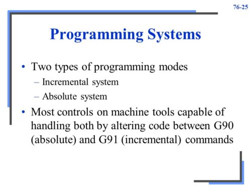
As an alternative to causing motion by rotating cranks and hand wheels as is required on orthodox machine tools, CNC machines let motion be controlled through programmed commands. Generally speaking, the motion type (rapid, linear, and spherical), the movement of the axes, the quantity of motion and the motion rate (feed-rate) are programmable with just about all CNC machine tools.
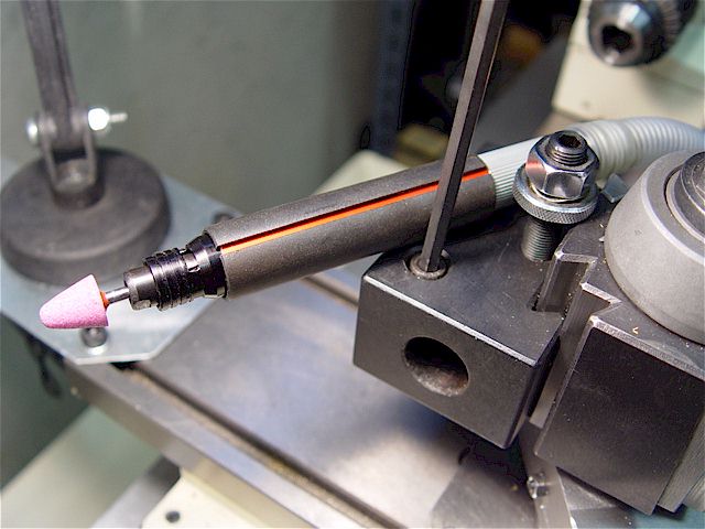
Precise positioning is accomplished by the machinist counting the number of revolutions completed on the hand wheel plus the advancements on the dial. The drive motor revolves at a corresponding rate, which in turn pushes the ball screw, causing linear motion of the axis. A feedback device ensures that the proper sum of ball screw revolutions have ensued.
A rather basic analogy, the same basic linear motion can be found on a usual table vise. As you swap the vise crank, you rotate a lead screw that drives the movable jaw on the vise. By assessment, a linear axis on a CNC machine tool is very precise. The number of revolutions of the axis drive motor accurately controls linear motion along the axis.
The program zero point ensures the point of orientation for motion commands in a CNC program. This lets the programmer specify movements from a common location. If program zero is selected wisely, it typically organizes the information needed for the program so it can be taken straight from the print.
With the illustrations given so far, all points happened to be up and to the right of the program zero point. This area up and to the right of the program zero point is known as a quadrant (in this case, quadrant number one). It is not rare on CNC machines that end points wanted within the program fall in other quadrants. When this occurs, at least one of the coordinates must be stated as minus.