Difference Between BT and HSK Tool Holders
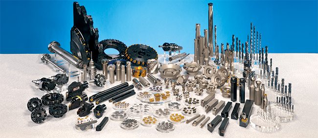
Introduction to BT and HSK Tool Holders

HSK Tool holders and BT Tool holders are some of the best available. CNCers searching for high precision tools to enable them to craft their projects with a high degree of precision and accuracy can utilise these tooling items to their benefits.

Although tool holders and cutting tools play vital roles in any high-speed machining operations, tool holders have different types and brands. There are differences in the various brands of tool holders.

HSK tool holders, developed in Germany, are symmetrical tools aiming to help manufacturers and end users bore holes, cut through materials, and perform other forms of high-speed machining operations with top-notch quality.

BT tool holders are also symmetrical, but with greater stability and balance during high-speed operations. These tooling systems are similar in various aspects, but there are slight changes that make a big difference.

Whether BT or HSK tool holders, they generally have the same basic anatomy. You can see the key difference between BT and HSK tool holders in their anatomy.

Anatomy of Tool holders

Generally, tool holders (also called collet chuck or collet holder) have four partsL the retention knobs (or pull studs), the taper, the v-Flange, and the collet pocket.

1. Retention Knobs

A retention knob keeps the tool holder in the spindle. When you use the wrong retention knob, the tool holder may fly out of the spindle during machining operations. This situation may be unsafe and dangerous to the machine operator. In some cases, retention knobs have a hollow-like pattern, allowing coolants to flow through the tool holder. During operations, the clamping set (in the spindle) holds the retention knob, pulling the tool holder up into the mouth of the spindle.

2. Taper

This is the part of the tool holder that has a conical shape. Normally, the taper has a tolerance level of 0.0002″ for both the outer diameter tolerance and the taper tolerance. Usually, the taper’s of the HSK tool holders are relatively shorter than that of BT holders.

3. V-Flange

This is the part of a tool holder that locks into the automatic tool changer during machining operations, especially when the tool moves in a to-and-fro pattern from the tool changer to the spindle.

4. Collet Pocket

This is the part of the tool holder where the collet goes in and collet nuts secure it.

BT and HSK Tool Holders – The Major Differences

HSK tool holders are widely used across the United States. Despite its popularity and high market acceptance, this tool holder is widely misunderstood.  Users fail to grasp the full potential and application of HSK tool holders.

Unlike HSK tool holders, whose full functionality is not understood, BT Tool holders have high market acceptance, and they’re symmetrical in the spindle axis. That makes BT tool holders have great balance and stability during high-speed machining operations.

Some of the basic difference between HSK and BT Tool Holders are:

1. Taper:

One of the basic difference between BT and HSK tool holders is the taper ratio. The HSK tool holders have a 1:10 taper while the BT ones use a 7:24 taper.

2. Dual Contact Point:

The dual contact nature of HSK tool holders is really striking. The spindle contacts with the taper and flange, while BT holders have the spindle in contact with the taper alone.

3. The positioning of the Drawbar:

The drawbar fingers in HSK tool holders are inside the shank while in the BT tool holders they are wrapped about the exterior surface of the retention knob as it holds the tool holder inside the spindle.

Manifestation of these Major Differences During High-Speed Machining

HSK tool holders offer repeatability, accuracy, and fast tool-changing. Although BT holders are of great value, they show some limitations at a high spindle speed of 8,000 rpm.

The BT heavyweight of 40 or BT 50 tool holders offers some sense of security while an HSK adapter of the same dimension is relatively lighter. Notwithstanding, the lightness of HSK tool holders is of great benefit during high rotational motions, making them outperform BT holders during high-speed machining operations. During high-speed machining, radial and axial heat growth occur at the spindle shaft and taper.

In the BT holder, radial growth occurs, pulling the tool holder deeper into the taper. This leads to a loss of accuracy on the Z-axis. Due to the hefty mass of the BT tool holder, heat growth is slow, causing the loss of a solid fit and radial stiffness of the taper. The gradual loss of the solid fit gives way to the development of chatter (or resonance).

When HSK tool holders are subjected to thermal effects, the retention system cannot pull the HSK adapter from its place. This is due to the axial location of the HSK adapter and the flange-to-flange connection with the spindle nose. In addition, the HSK taper shank and the spindle taper tend to heat and grow evenly.

Unlike BT holders, the high-speed rotation has a positive impact on HSK tool holders as their grip increase as rotational speed does, which leads to a corresponding increase of the centrifugal force.

Ultimately, HSK tool holders have better radial and axial stiffness, leading to high accuracy, repeatability, and top-notch surface finishing.

With HSK tool holder types A, B, C, D, E, and F, users have a wide variety of options for a specific project.

Conclusion – BT or HSK Tool Holders?

HSK tool holders

BT tool holders have served us well in the past in several low-speed cutting projects.
On the other hand, HSK tool holders are high-speed machining tools designed for the future as they’re of immense value for both low speed/high torque applications and high speed/low torque applications.

Although each tool holder has a unique design with its advantages and disadvantages, HSK tool holders are a better choice for manufacturers and end users looking for tool holders with greater precision and accuracy.

Either way you decide, if you want to buy HSK tool holders or BT tool holders, we’ve got you covered! Just fill out the form on the right!

Reference article

Tool Holders 101: Cat, BT, HSK and More Info

Tool holders (toolholders) are the main facet that connects the machine tool to the tooling.. Their mounting styles are all different according to the interface. Their mounts can range from HSK tool holders, VDI mount, or the dated R8 styles.

All types of tool holders consist of 3 unique parts: the collet pocket, the flange, and the taper. There is static tooling which is not powered and there is live (driven) tooling which is not powered.

  • Taper: The taper part of a toolholder is cone-shaped. It is the part that is connected to the spindle when the tool is changed.
  • Flange: The flange is connected and attached to the automatic changer which moves the spindle and tool changer.
  • Collet Pocket: The collet pocket is fastened to the different collet nuts and is the region where the insert of the collet is secured.

A variety of tool holders surround the cutting tool (machine tool) so it remains intact in one position – while many other machining tools enable maximized clearance for small to large sizes.

Tool Holder Types

There are a wide variety of tool-holder types, they are indexed in the industrial machine tooling databases as such:

  • Machine arbors: These are driven by motors an are responsible for the turning mechanism of machinery tools.
  • Side cutter holders: These toolholder’s purpose is to hold the cutting tools in place.
  • Saw blade holders: These holders keep saw-blades in place.
  • Boring heads: They hold boring bars in places as well as other types of tool holders.
  • Tapping chucks: These keep operations in threading running smooth and also keep tapping tools in place.
  • Blank adapters: Depending on tasks in machining these are customizable for various applications.
  • End mill holders: Essentially for milling, these holders keep milling tools in place.
  • Outer diameter (OD) and inner diameter (ID): These are universal holders that are interchangeable with many types of tools for cutting.
  • Collet chucks: The variety of collet chucks work to hold different machinery tooling in place.
  • Milling or drilling chucks: Specifically designed to hold the placement for tools associated with drilling and million operations.

When you but tool holders, you should consider the exact mounting style that you need..

R8 is an old school mount developed by Bridgeport back in 1965. This part is obsolete and rarely used in modern machine tooling.

 The Morse taper (MT)  is manufactured in 4 different sizes. Every size differential contains a unique taper for ease of transitional changes in tool fittings and machinery tool use.

National Machine Tool Builders (NMTB) defined

The NMTB taper  type of toolholder was defined by (NMBT) National Machine Tool Builders. It is used in all types of milling CNC machinery and machines. The basic measurement requires a draw bar and stands at 3.5 inches per foot.

The CAT®  by Caterpillar®developed  customized mount style, is mainly referred to the  V-flange. It is the very basic tool for Cat CNC machines. All tool-holders built and manufactured by Cat consist of a numerical ID associated with taper size. (examples CAT-30, CAT-40, CAT-50 and CAT-60.)

Similar to the popular Cat tooling options is also BT tool holders. BT holders differ from cat because they are all symmetric and balanced within the rotational axis. BT toolholders contain the same standards of taper measures as the NMBT stud threads that use metrics to move.

Hollow shank tooling (HSK)  is a new innovation in tooling that is now used and implemented with various types of HSM machines. It is manufactured for quick changes in tooling and also comes in straight shank formats and dovetail formatting in machinery.


Tool Holders: Features and Applications

Tool holders features and application widely vary from those who have open coolant flow through the flange or are openly fed by components. Such models, brands, and makes (i.e.. Cat tool holders, BT tool holders, and HSK tool holders) are every bit (no pun intended) of the best examples for this instance. Every one varies in application and interchangeable abilities to adapt to size changes from small to large with the most gap of clearance possible. It is important to understand that every tool holder manufactured is tailored and customized for its specific purpose, task, and job. This makes a vast difference in operational and performance efficiency for use.

What Are CNC Offsets?

Every practice of compensation has to do with offsets (especially in regards to CNC offsets)!

One can consider CNC offsets as memories on an electronic calculator. If your calculator has memory, you can store a constant value to each memory for use throughout a calculation. This keeps one from having to enter the number over and over again.

Like the memory of an electronic calculator, offsets in the CNC control are stored locations into which mathematical values can be entered. Just as the value in the memory of a calculator has no sense until referenced by its operator in a calculation, the value contained by an offset of the CNC regulator does not have any significance until it is referenced by a CNC program.

From the marksman analogy, one can think of the values deposited in CNC offsets as the sum of modification necessary on the prospect of the search needed to compensate for detachment to the aim. Remember that the rifle only requires alteration for one resolution, to modify for the detachment to the aim. With most CNC machine tools, it is necessary to have at least one offset for each tool.

Read more about your machines at our blog here.

Causes of tool offsets
kakouB2_1
Offsets can be recycled for numerous determinations dependent on the style of device tool and sort of compensation being used. Here are some of the more collective presentations for offsets.

For machining midpoint applications, it would be very problematic for the programmer to forecast the exact length of every tool used in the program.

To this end, the feature tool length compensation trusts the programmer to check every tool’s length as the program is written. During the setup, the programmer measures the length of each tool and inputs the tool length value into the equivalent offset.

While milling on the edge of the cutter (contour milling), it can problematic for the programmer to program the cutter’s track founded on the size of the milling cutter being used. Similarly, if the cutter size must modify (possibly due to re-sharpening), it would be impractical to modify the program based on the fresh cutter size.

For this reason, the feature cutter radius compensation lets the program writer override the cutter size as the program is inscribed. The operator inputs the size of each milling cutter into its corresponding tool offset. In the same manner, rotating centers have a feature named tool nose radius compensation. With this feature, an offset is used to identify the radius of the very tip of the turning or boring tool.

Machining centers that have match offsets (also called coordinate system shifting) let the worker identify the location of the program zero point within offsets, keeping the assignment of program zero separate from the program. In the same way, many rotating centers allow the assignment of program zero via offsets (this feature is usually named geometry offsets).

Tool offsets are used on all turning centers to let the worker grip size with tools used in their programs. This permits the worker to regulate for flaws with tool settlement during setup. It also permits the worker to regulate the tool’s movements to permit for wear throughout every tool’s lifespan.

Ref: CNCCI

Go to Top