CNC Cutting Tools: All You Need To Know
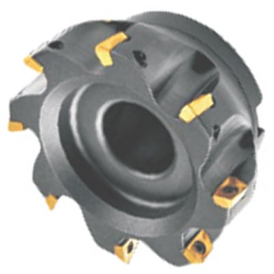
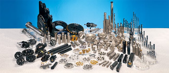
CNC Cutting Tools: Types, Materials, and Uses Computer Numeric Control (CNC) machines are computer-driven, high-precision tools that repeat the same movements with tight accuracy. The technology traces back to the 1940s and 50s, when numerically controlled machines first reached industry, and it now runs in nearly every manufacturing sector. The tool that actually removes metal [...]