Difference Between BT and HSK Tool Holders

Introduction to BT and HSK Tool Holders

HSK Tool holders and BT Tool holders are some of the best available. CNCers searching for high precision tools to enable them to craft their projects with a high degree of precision and accuracy can utilise these tooling items to their benefits.

Although tool holders and cutting tools play vital roles in any high-speed machining operations, tool holders have different types and brands. There are differences in the various brands of tool holders.

HSK tool holders, developed in Germany, are symmetrical tools aiming to help manufacturers and end users bore holes, cut through materials, and perform other forms of high-speed machining operations with top-notch quality.

BT tool holders are also symmetrical, but with greater stability and balance during high-speed operations. These tooling systems are similar in various aspects, but there are slight changes that make a big difference.

Whether BT or HSK tool holders, they generally have the same basic anatomy. You can see the key difference between BT and HSK tool holders in their anatomy.

Anatomy of Tool holders

Generally, tool holders (also called collet chuck or collet holder) have four partsL the retention knobs (or pull studs), the taper, the v-Flange, and the collet pocket.

1. Retention Knobs

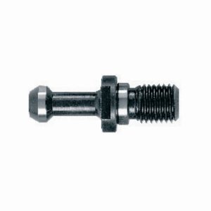
A retention knob keeps the tool holder in the spindle. When you use the wrong retention knob, the tool holder may fly out of the spindle during machining operations. This situation may be unsafe and dangerous to the machine operator. In some cases, retention knobs have a hollow-like pattern, allowing coolants to flow through the tool holder. During operations, the clamping set (in the spindle) holds the retention knob, pulling the tool holder up into the mouth of the spindle.

2. Taper

This is the part of the tool holder that has a conical shape. Normally, the taper has a tolerance level of 0.0002″ for both the outer diameter tolerance and the taper tolerance. Usually, the taper’s of the HSK tool holders are relatively shorter than that of BT holders.

3. V-Flange

This is the part of a tool holder that locks into the automatic tool changer during machining operations, especially when the tool moves in a to-and-fro pattern from the tool changer to the spindle.

4. Collet Pocket

This is the part of the tool holder where the collet goes in and collet nuts secure it.

BT and HSK Tool Holders – The Major Differences

HSK tool holders are widely used across the United States. Despite its popularity and high market acceptance, this tool holder is widely misunderstood.  Users fail to grasp the full potential and application of HSK tool holders.

Unlike HSK tool holders, whose full functionality is not understood, BT Tool holders have high market acceptance, and they’re symmetrical in the spindle axis. That makes BT tool holders have great balance and stability during high-speed machining operations.

Some of the basic difference between HSK and BT Tool Holders are:

1. Taper:

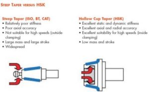
One of the basic difference between BT and HSK tool holders is the taper ratio. The HSK tool holders have a 1:10 taper while the BT ones use a 7:24 taper.

2. Dual Contact Point:

The dual contact nature of HSK tool holders is really striking. The spindle contacts with the taper and flange, while BT holders have the spindle in contact with the taper alone.

3. The positioning of the Drawbar:

The drawbar fingers in HSK tool holders are inside the shank while in the BT tool holders they are wrapped about the exterior surface of the retention knob as it holds the tool holder inside the spindle.

Manifestation of these Major Differences During High-Speed Machining

HSK tool holders offer repeatability, accuracy, and fast tool-changing. Although BT holders are of great value, they show some limitations at a high spindle speed of 8,000 rpm.

The BT heavyweight of 40 or BT 50 tool holders offers some sense of security while an HSK adapter of the same dimension is relatively lighter. Notwithstanding, the lightness of HSK tool holders is of great benefit during high rotational motions, making them outperform BT holders during high-speed machining operations. During high-speed machining, radial and axial heat growth occur at the spindle shaft and taper.

In the BT holder, radial growth occurs, pulling the tool holder deeper into the taper. This leads to a loss of accuracy on the Z-axis. Due to the hefty mass of the BT tool holder, heat growth is slow, causing the loss of a solid fit and radial stiffness of the taper. The gradual loss of the solid fit gives way to the development of chatter (or resonance).

When HSK tool holders are subjected to thermal effects, the retention system cannot pull the HSK adapter from its place. This is due to the axial location of the HSK adapter and the flange-to-flange connection with the spindle nose. In addition, the HSK taper shank and the spindle taper tend to heat and grow evenly.

Unlike BT holders, the high-speed rotation has a positive impact on HSK tool holders as their grip increase as rotational speed does, which leads to a corresponding increase of the centrifugal force.

Ultimately, HSK tool holders have better radial and axial stiffness, leading to high accuracy, repeatability, and top-notch surface finishing.

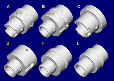
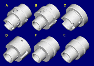
With HSK tool holder types A, B, C, D, E, and F, users have a wide variety of options for a specific project.

Conclusion – BT or HSK Tool Holders?

HSK tool holders

BT tool holders have served us well in the past in several low-speed cutting projects.
On the other hand, HSK tool holders are high-speed machining tools designed for the future as they’re of immense value for both low speed/high torque applications and high speed/low torque applications.

Although each tool holder has a unique design with its advantages and disadvantages, HSK tool holders are a better choice for manufacturers and end users looking for tool holders with greater precision and accuracy.

Either way you decide, if you want to buy HSK tool holders or BT tool holders, we’ve got you covered! Just fill out the form on the right!

Reference article

CNC Cutting Tools: All You Need To Know

Introduction to CNC Cutting Tools

In the modern manufacturing world, Computer Numeric Control (CNC) machines are widely used. CNC machines are computer-controlled, high-precision tools designed to make accurate movements in a repeated pattern. During the 1940s and 50s, CNC cutting tools were introduced in the industrial world. These high-precision machines were used for various machining operations. In recent years, these automated machine tools have been widely applied in all manufacturing industries.

Although CNC machining is very similar to 3D printing, the key difference lies in their high precision, advanced speed, and cost. Generally, the CNC machine is a better choice for more precise, efficient, and top quality projects.

There are various types of CNC cutting tools and these tools are designed for high-precision machining. Most often, manufacturers make use of CNC cutting tools for near-perfection projects requiring a high degree of accuracy and precision. Which of the CNC cutting tools used is dependent on the project, operation pattern, and, most importantly, the CNC machine itself. Before we discuss CNC cutting tools, let’s take a closer look at the various types of CNC machines.

Types Of CNC Cutting Machines

Basically, there are five broad types of CNC machines and the CNC cutting tools used are dependent on the type of machine, nature of the project, and overall precision required for the project. The five broad types of CNC machines are:

CNC cutting toolsCNC Milling Machine

  These are arguably the most common CNC machines on the market. Specific programs in terms of letters and numbers are translated in the CNC mills. A programming language called G code is utilised in these machining operations.

Being pre-programmed, rotary cutting tools cut pieces of metals into different shapes and sizes.
Unlike other manual-operation milling machines, the CNC milling machine has greater precision and high accuracy.

CNC cutting tools

CNC Routers

Like most manually operated routers, CNC routers cut materials such as wood, plastic, steel, aluminium, foam, and composites. But with the CNC routers, you’ll be able to cut more prototype models and advanced shapes of materials. Like the CNC mill, the CNC router runs with a numeric computer control, improving productivity as it produces more items in less time. Normally, industrial CNC routers have 3-axis machines. But technical and high complex machining operations use 4-axis, 5-axis, and 6-axis machines.


 CNC Lathes

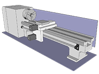
Operating with the various programming language, these machines produce more precise cuts. These are rotatory machines that make precise cuts, 3D shapes and moulds of materials by their spinning actions. These machines are ideal to manufacture spherical or cylindrical objects.


Plasma Cutters

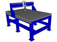
CNC plasma cutters use a plasma torch to cut heavy metals like steel. This functions through the conversion of gases that the cutter blows at high speed into plasma. The plasma, which is usually very hot, melts any metal the machine is cutting. Pieces of metals at the cutting site are also blown away by the high pressure.

Electrical Discharge CNC Machines

Electrical Discharge Machines can be virtual or wire machines. These machines use electric sparks to cut through metal sheets. With this, they create specific shapes and sizes of materials.

Aside from these five types of CNC machines, other types are available in the market. With the advent of CNC machines, manufacturing has been made easier as more precise and accurate projects can be done at the least possible time.

CNC CUTTING TOOLS

Since ancient times, cutting tools have existed. They’re one of the oldest inventions in human history andnd there has been a dramatic change in the type of cutting tools we use. Initially, we built them with stones, so these metallic tools are of much value in the manufacturing world.

Although all cutting tools serve one purpose, to cut through a material, there is a huge difference in their purpose.
Normally, for a cutting tool to be effective, it has to:

  • be 30% to 50% harder than the material it will work on.
  • be easily fabricated.
  • have high thermal conductivity.
  • have low coefficient of friction.
  • be very resistance to wear.
  • be chemically inert and stable.

In practice, different CNC cutting tools perform cutting operations. Before considering which CNC cutting tools to use for a specific operation, you’ve got to understand the material that manufacturers used when producing the tool. Based on that material, we classify cutting tools into:

Carbon Steel Tool

These cutting tools are inexpensive and are mainly for low-speed operations. They have a carbon composition of 0.6 – 1.5% with a little amount of manganese and silicon. They’re mainly in twist drills, forming tools, milling cutters, and turning.


High-Speed Steel (HSS)

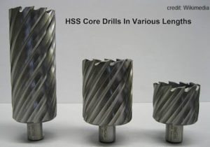
It‘s composed of high carbon steel with a reasonable amount of element alloys like chromium, tungsten, and molybdenum. With this combination, it improves hardness, wear resistance, and toughness. It also offers higher removal rate for metals and other materials. To improve its property, you’ve got to apply certain surface treatment.

Ceramics

These chemically inert tools are corrosion-resistant and 10x faster than high-speed steel. Usually,aluminum oxide and silicon nitride make up ceramics materials. Projects that require top-notch finish operations normally use ceramics.


Cemented Carbide

Designed for high-speed operations, these carbide tools are extraordinarily hard and can withstand temperatures of up to 1000oC. Normally, tantalum, titanium, and tungsten make them up. Operations that require a high-quality surface finish also use them.
Other classifications include diamond tools, cubic boron nitride (CBN), sialon, and cermets.

CNC Cutting tools come in various shapes and sizes and you can use them for various milling and lathe cutting operations.

Some CNC cutting tools are:

End Mills

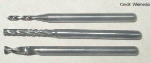
Rotational cutting tools that you can use for the removal of materials. Although very similar to the drill bit, the end mill is for more versatile machining operations. Unlike the drill bit that cut axially to the material, end mills are lateral cutting tools that cut in any direction. Due to their design, some end mills cannot cut materials axially.

Generally, there are different types of tip shapes for an end mill and each end mill depends on the desired end-product. The various types of end mills are:

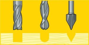
Ball nose mills: Ideal for 3D contour work, ball nose mills have rounded ends that produce top-notch curved surfaces.


V-bit: Depressions that these tools make are V-shaped. V-bit can be 90or 60and each depends on the angle of depression that a material needs. Although they often use them to engrave signs on materials, they’re ideal for projects that need excellent sharp edges.
Straight Flute End Mills: These CNC cutting tools are general purpose tools that offer top quality edges.
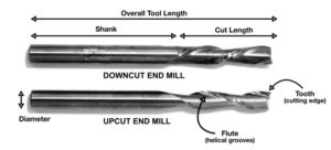
Down-cut and up-cut end mills: These spiral tools can either produce a smooth-surface finish by carrying the residue chips down or a rough-surface finish by carrying the residue up and away from the specified area.


The basic anatomy of an end mill consists of a flute (helical grooves), cutting edge (teeth), diameter, shank, cut length, and the overall tool length.

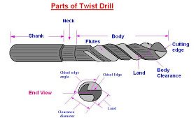
2. Twist Drills: These rotary CNC cutting tools have two flutes and two cutting edges. Through their unique designs, coolants can quickly reach the point of cut action. Manufacturers usually use these cutting tools to lower production costs and perform operations with top-notch finishing.


The twist drill is comprised of three major parts: The shank, the body, and the point.

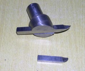
3. Fly Cutter: These single point cutters are on a mill and general purpose fly cutters provide excellent surface finishes.

This CNC cutting tool goes across the surface of a material through a clockwise rotation, making the material surface smooth and flat. The fly cutter is for CNCers who want to produce an outstanding fine finish.

4. Cutting Fluids and Coolants: Typically not a CNC cutting tool, cutting fluids flush material chips away from the cutting zone. They also offer additional benefits like:

  • Reduction of thermal deformation in a workpiece.
  • Improvement of the tool life.
  • Surface finish improvement.

Tool holders typically hold CNC cutting tools before fitting them into the CNC machines. The quality, design, and manufacturer’s specifications about the tool holders are critical to an overall success of the machining operations.

Why Should You Make The Right Choice with CNC Cutting Tools? 

Cutting tools play a vital role in the quality of projects done. Although buying these items might be pricey, you cannot overlook their importance. In fact, the quality of your project depends on the kind of cutting tool you use.

The industrial world is highly competitive and, to succeed, manufacturers and end-users have to build top-notch products through proper planning and precise cutting. Since cutting tools form the backbone of a professional project, you need to pay special attention to these little items that can make or mar your projects.

Greater productivity, high precision, accuracy, and efficiency in machining operations are the driving force needed to craft top-notch products. You can easily achieve these features by having the right cutting tools and having an in-depth knowledge about  CNC cutting tools is the first step towards success in a competitive industry.

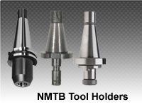
NMTB Tool Holders

Introduction to NMTB Tool Holders

NMTB tool holders (National Machine Tool Builders Association), another name for “Quick-Change”, come in different sizes and they’re mainly single-flanged. You can tell the taper size from their number: NMTB 25, NMTB 30, NMTB 35, NMTB 40, NMTB 45, NMTB 50, NMTB 55, and NMTB 60. The smallest tool holder (NMTB 25) normally goes on small machines, while the largest (NMTB 60) goes on larger ones. NMTB tool holders is a national association that focuses on building machine tooling systems such as the NMTB shank and spindle and other tooling systems.

Unlike other tooling systems, NMTB tool holders have a drawer. As single-flanged tool holders, there are two keyways that go onto a simple flange. Although NMTB tool holders are relatively old, they still fit into modern machining systems. Numerous manufacturers make these tool holders, making it difficult to have uniform dimensions for all NMTB tools.

In most cases, the flange thickness, diameter, and length from the taper’s gage line do not determine the dimensions of the NMTB tools. NMTB tool holders are manufactured in such a way that most of their tooling system is compatible with other tooling systems, like Erickson Quick Change Spindle.

Aside from that one, other brands are also compatible with NMTB tooling system. In most cases, users are advised to find out more about the tool before making a decision. NMTB tool holders can fit into other tooling systems of the same dimension by simply changing out the lug bars. For instance, users can do tool-changing operations by fitting NMBT 30 into Cat 30 or BT 30.                                        

NMBT Face Tool Holders

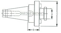
NMTB TOOLING imageThese holders are designed with an Arbor Screw Key and four mounting holes.

Some of its specifications are:

 Gage length of 2.25 inches. Flange diameter of 4 7/8 inches.  • Four mounting holes.   • A bolt size of four inches.

More NMBT face tool holders are available and the specifications are dependent on the user’s choice.

NMBT Shank

These tooling systems have drive keys and arbor screw. They can fit into Erickson Quick-Change holders and their main use is as adaptors.

The sizes and dimension of these shanks vary, making them suitable for various machining operations. NMTB tooling is mainly for high-speed machining operations and high-precision tolerance. End-users will find them useful as they’ll be able to complete their projects with high accuracy. One fascinating feature of NMTB tooling technology is in its compatibility with other quick change spindles:

NMTB Compatibility with other Quick Change Spindles

NMTB tooling systems are highly compatible with other tooling machines. But the thing is that each tool holder has to have an appropriate and corresponding quick change spindle of the same dimension. That is, NMTB 30 can fit into Cat 30 and BT 30 tool holders. NMTB 40 and NMTB 50 will fit into Cat 40 and Cat 50 respectively.

In the original NMTB shank design, a drawbar pulls up the shank into the spindle. As we said, there are different manufacturers of these tooling systems and the flange diameter, thickness, and the distance of its taper’s gage line to the flange’s outward face do not determine its dimensions. The Erickson Quick-Change spindle by Erickson Tool was designed to be compatible with NMTB tool holders. Erickson Quick Change’s design is such that you do not use the drawbacks. Instead, you use quarter turn lockouts to fit the tool taper into the spindle.

For this tooling setup to work, the tool flange’s outer face comes out of the projection, or “lips”, at the nut. In some cases, the NMTB tool holders don’t work with Erickson Quick-Change spindle due to the distance between the flange’s outer face and the taper gage line. This gage distance is large, making it difficult for the projection or “lips” of the quick change to fit into the flange’s face. Other issues occur when the flange diameter on some NMTB holders is too small and unable to fit into the mouth of the spindle.

Overcoming these issues involves a thorough examination of the NMTB tool holders and spindles. This is to ensure that the specifications by the manufacturers match. Generally, the Erickson Spindles works well with NMTB tool holders. Other brands that work well include Collis, Valenite, and Kennametal holders.

What Next?

Performing high-speed machining operations requires great precision and accuracy. Ultimately, you’ll need a tool holder that’s for the modern day world but is also compatible with other quick change spindles. NMTB holders offer great value for users aiming to complete their projects with near-PERFECT precision and accuracy. These amazing tool holders are manufactured with top notch designs and come in diverse sizes. Are you searching for tool holders for your professional or DIY projects? NMBT tool holders are there to serve your needs.

How Shrink Fit Tooling Works

Introduction to Shrink Fit Tooling

Shrink fit tooling is the leading choice for any high-speed machining operations. Although some argue that Collect Toolholder are better options, the reality still remainsL Shrink Fit tool holders are the best tooling technology for high accuracy and top speed machining.

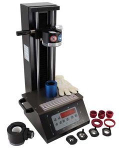
Shrink Fit Tooling Machine

With amazing features, such as outstanding grip power, excellent balance, and good indicator reading, shrink fit tooling will help you get more work done in less time.
Using the shrink fit tool holder will create a positive impact on your work as you’ll get high precision in all your projects, increase the lifespan of your tool and spindle, reduce the tool change time, and lower the cost of tool maintenance.
In fact, shrink fit tooling enables you to create, build, and design customizable holders for all applications. The flexibility and high accuracy of this tooling system are phenomenal.
In this article, we’ll unravel the working formula of shrink fit tooling systems.

How Shrink Fit Tooling Works

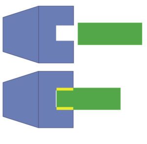
Shrink fit tooling technology utilizes heat-shrinking to clamp cutting tool shank in high-speed machining. This quick-change tool holding process in high-speed machining in highly efficient and it saves production time for the user.
This process is simple as the shank cutter tool is inserted into the shrink fit tool holder. The interior diameter of the shrink fit tool holder is a little smaller than the diameter of the shank cutting tool.

Working Mechanism

This interior bore of the tool holder expands with heat. As the bore grows to a sufficient size, the tool cutter automatically slides into the bore. At this point, cooling begins and the bore shrinks, exerting uniform pressure (about 10,000 lbs of force) on the surface of the cutting tool shank. This results in a tremendous gripping strength on the whole surface of the tool shank.


The reverse process happens when you remove the tool. Shrink fit tooling technology makes it possible to accomplish tool changes within seconds, which in turn improves productivity during high-speed machining.
Manufacturers find shrink fit tooling systems useful as they’re able to do more work by reducing the time they spend on changing tools. End-users, on the other hand, can utilize this amazing technology to greatly increase their productivity.

Heating Systems in Shrink Fit Tooling Technology

The three heating systems in shrink fit tooling technology are: open flame, induction heating, and hot air.

Induction heating makes use of high-frequency current that flows through a metal coil. Here, you insert the tool holder into the metal coil and a high-frequency eddy current heats it up as the temperature greatly increases.

How Shrink Fit Tooling Works image of tools

People usually install infrared temperature sensors to monitor the tool holder’s temperature. This serves as a safety measure for the proper control of the tool holder’s temperature and regulating the current in the metal coil. Induction heating is the best heating system available in the market.
Like induction heating, open flame and hot air systems function by heating the surface of the tool holder. The difference lies in the degree to which heat goes to the holder.
Unlike induction heating, hot air and open flame heat the holder more slowly, leading to little temperature variations between the tool cutter and holder. These heating systems are relatively less expensive and more economical than induction heating ones.
The cooling system in shrink fit tooling systems could be air or liquid filled coolants. These two cooling systems typically function through a 20k to 50k shrink/unshrink cycles.

Shrink fit tooling systems’ features include:

Concentricity

The concentricity of the shrink fit tool is outstanding, as it is below three microns. You’re guaranteed 0.00012″ (3 microns) run-out at three times the diameter of the cutting tool. With this high concentricity, the tool cutter and holder function like a single piece. This high level of accuracy is repeatable for all operators.

Balance

In the absence of moving parts, shrink fit holders offer the best balance repeatability of all tool holding systems available. Shrink fit holders come with the highest accuracy and balance standards. Special designs are also available at a tolerance level of G 1.0 at 30,000 RPM. This provides higher feed rates, speeds, balanced chip loads, and better finishes.

Rigidity

The cutting tool has 360 degrees grip on multiple planes around the shank. This results in an extremely high gripping torque that prevents any irregular movement of the cutting tool during roughing or finishing operations. This, in turn, results in the reduction of scrapped pieces.

Tool life Extension

Shrink fit tooling technology extends tool life by over 100%. Their concentricity, gripping force, and balance help you increase productivity and ultimately extend tool life by a wide margin.
Do you want a long lasting tool? Shrink fit tooling technology is the best for your needs.

Extremely High-Speed Operation

Shrink fit tooling is the go-to for any high-speed machining operations. Their clamping force along with their superior system makes them the best choice for any high-speed machining operations.
Unlike mill and hydraulic chucks, shrink fit tooling offers extraordinary concentricity, making it outperform other brands in the market.

Benefits of Shrink Fit Tooling Technology

1. Superb accuracy.
2. High gripping torque.
3. Extension outlets that offer you diverse options with standard products.
4. Reduction in tool-changing time. This, in turn, leads to greater productivity.
5. Setup cleanliness, leading to cleaner bores and less contamination. This is because shrink fit tooling is a sealed system.
6. Outstanding coolant options, which both aid in cooling and in delivering fine finishing.
7. Cost reduction. The cost of tool changing is far lower if you use shrink fit tooling systems.
8. Availability. Shrink fit tooling systems are readily available and having one of them guarantees quick tool changing and greater productivity.

Conclusion

Although other tool holders are available in the market, shrink fit tooling makes it easier to change tools at a very fast pace, reducing tool changing time and increasing productivity.
As the most economical tool system, shrink fit tooling increases tool life, reduces cost, and ultimately helps manufacturers and end-users get more work done.
As a plant manager, shop owner, or manufacturer, shrink fit tooling will be the best investment you’ll make, guaranteeing you a boost in productivity.

HSK Shanks and Receivers: A Primer

HSK Shanks and Receivers – Introduction

Speed, accuracy, precision, and faster tool changes are the benchmark and differentiating factor in the manufacturing world. Modern manufacturers are always looking for ways of improving their products in the shortest possible time. HSK shanks and receivers are tools with which these manufacturers can do just that.

In order to outperform your competitor, you’ve got to have the right set of tools. Tools that provide the fastest removal rates, rigidity, and accuracy. Tools with high precision and rigidity: The HSK tooling technology.

HSK is an acronym for Hollow Taper Shank.

image of hsk shanks

HSK shanks and receivers have the purpose of bringing high rigidity, accuracy, and greater stability in high-speed machining.

In the quest to fill in the gap for top-notch tooling system, a non-proprietary model was introduced in Germany. These HSK shanks and receivers have become more popular across the US in the last few years.

With its increasing popularity across the US market coupled with an outstanding tooling system, productions were reversed and manufacturers found a tool holder with higher standards for their future projects.

One of the key differentiating factors in HSK tools is in the degree of tolerance. The tolerance between the taper and the spindle receiver is below two microns (.002 mm). These tools supports Automated Tool Change (ATC).
Different manufacturers produce HSK shanks and receivers and every type serves a specific need.

Types of HSK Shanks and Receivers

There are six types of HSK shanks and they’re available in 35 sizes. Spindle receivers are also designed for each shank type. Your choice of shanks is dependent on the spindle speed and torque.

HSK shanks and receivers

Types of HSK Shanks

Description of Types of HSK Shanks and Receivers

  • A: for automatic tool-changing for applications operating with moderate to high revolution and those on a high torque.
    Normally, these applications should have a revolution speed above 12 rpm and below 25,000 rpm.
  • B: for automatic tool changing for applications operating with high torque and also on a moderate to high spindle speed.
  • C: for manual tool-changing for applications operating with moderate torque and on a moderate to high revolution speed.
  • D: for manual tool-changing for applications operating on high torque with moderate to high revolution speed.
  • E and F: to support the Automated Tool Change (ATC) technology and for applications operating with low torque and extremely high revolution speed.

Why Should You Use HSK Shanks and Receivers?

Over the years, there has been a dramatic change in the use of tools in the manufacturing world. End users, on the other hand, are searching for reliable, easy, and fast tools to help them finish their projects with the highest level of precision and accuracy.

HSK tools not only make your work faster, they also make it easier without wasting time during the coupling of the basic component parts of the system.

Unlike other conventional tool holders, like BT, NMTB, and CAT V-flange, which are largely for high-speed machining, HSK tool holders increase grip and rigidity as the revolution speed increases. The shorter taper acts as a safety measure to stop pulling out the holder from the spindle at high revolution speed.

HSK tools reduce the cycle time to facilitate faster operations while other conventional tools are relatively slower.

A lightweight structure coupled with the stiffer and precise operation styles make HSK tools the best tools for the future.
Generally, HSK tool holders are becoming increasingly important for any high-speed machining operations. The aerospace and automotive industries predominantly use them.

Manufacturers and end users looking for accurate, lightweight, and easy-to-use tool holders can utilize the amazing value in HSK shanks and receivers.

The Main Benefits of Carbide Tools

The carbide tooling industry is booming! The demand cannot even be met in a timely manner by the distribution, development, and creation of new carbide cutting tools. As this demand continually increases, suppliers of cutting tools are working diligently to handle the heavy load of developing more innovative and high-performance cutting tool products to meet such a overwhelming demand.
One of the main sources of cutting tools in this society is that of tungsten, carbide tools- which are mainly moneoplized overseas in China. It has been a long process to weed out the best from the useless when it comes to cutting tools, but in the end – it boils down to high performance, cutting- edge, quality tools that make the grade!

In the industry of machining, there are 2 main-stay types of tools that make the grade: CARBIDE based tool for cutting and high-speed tooling (HSS) for cutting. However, most recently it appears that Carbide tools have monopolized the industry as the most popular of the two.

So if statistics and popularity say anything, what is the most benefits of carbide tools that people are choosing over HSS tooling?  Taking into consideration the vast new popularity and consensus that carbide tooling is the bomb – we are certain that the benefits of carbide vs. HSS are far better. But let’s take a lookey to really see….

What is Carbide?

Carbide is an essential element (chemical compound in substance) that is often combined with another natural element on the chain such as boron, silicon, metal,  or steel. In this grouping of a combination of solid elements and carbide, these are the most prominent:

– Calcium Carbide
– Aluminum Carbide
– Silicon Carbide
– Tungsten Carbide
– Iron Carbide

The Benefits of Carbide Tools:

  • Tools made of Carbide are cheap and effective in comparison to other types of HSS tooling options. They are durable at most and also can endure high-temperatures, turning at a very high-speed – this type of exposure wears other types of tooling metals down.
  • Carbide-based tool holders and machine tools consist of a large durability that enable them to have a longer shelf-life as they retain their cutting tool edges.
  • Carbide tooling allows you to acquire better performance when it comes to finish and surface-finish quality.
  • Carbide tools run lower in cost than other types of tools. They are very durable and are resilient to cracking.
  • Carbide tools are of the best quality, and when it comes to costs they are the most inexpensive for quality toolholder types and makes that you can purchase. For the longevity and shelf life of carbide tooling it is ultra cost effective to not need to purchase tools every so often.

There are tons of benefits to carbide tools, and that is one of the main reasons why they are the most popular of the  metals used for the manufactyring of toolholders. They are cost-effective, durable, and their diverse nature makes them more than pricesless to mechanics who use CNC and lathe machine sin the industry!

Tool Holders 101: Cat, BT, HSK and More Info

Tool holders (toolholders) are the main facet that connects the machine tool to the tooling.. Their mounting styles are all different according to the interface. Their mounts can range from HSK tool holders, VDI mount, or the dated R8 styles.

All types of tool holders consist of 3 unique parts: the collet pocket, the flange, and the taper. There is static tooling which is not powered and there is live (driven) tooling which is not powered.

  • Taper: The taper part of a toolholder is cone-shaped. It is the part that is connected to the spindle when the tool is changed.
  • Flange: The flange is connected and attached to the automatic changer which moves the spindle and tool changer.
  • Collet Pocket: The collet pocket is fastened to the different collet nuts and is the region where the insert of the collet is secured.

A variety of tool holders surround the cutting tool (machine tool) so it remains intact in one position – while many other machining tools enable maximized clearance for small to large sizes.

Tool Holder Types

There are a wide variety of tool-holder types, they are indexed in the industrial machine tooling databases as such:

  • Machine arbors: These are driven by motors an are responsible for the turning mechanism of machinery tools.
  • Side cutter holders: These toolholder’s purpose is to hold the cutting tools in place.
  • Saw blade holders: These holders keep saw-blades in place.
  • Boring heads: They hold boring bars in places as well as other types of tool holders.
  • Tapping chucks: These keep operations in threading running smooth and also keep tapping tools in place.
  • Blank adapters: Depending on tasks in machining these are customizable for various applications.
  • End mill holders: Essentially for milling, these holders keep milling tools in place.
  • Outer diameter (OD) and inner diameter (ID): These are universal holders that are interchangeable with many types of tools for cutting.
  • Collet chucks: The variety of collet chucks work to hold different machinery tooling in place.
  • Milling or drilling chucks: Specifically designed to hold the placement for tools associated with drilling and million operations.

When you but tool holders, you should consider the exact mounting style that you need..

R8 is an old school mount developed by Bridgeport back in 1965. This part is obsolete and rarely used in modern machine tooling.

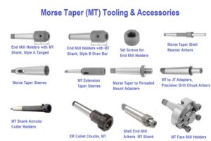
 The Morse taper (MT)  is manufactured in 4 different sizes. Every size differential contains a unique taper for ease of transitional changes in tool fittings and machinery tool use.

National Machine Tool Builders (NMTB) defined

The NMTB taper  type of toolholder was defined by (NMBT) National Machine Tool Builders. It is used in all types of milling CNC machinery and machines. The basic measurement requires a draw bar and stands at 3.5 inches per foot.

The CAT®  by Caterpillar®developed  customized mount style, is mainly referred to the  V-flange. It is the very basic tool for Cat CNC machines. All tool-holders built and manufactured by Cat consist of a numerical ID associated with taper size. (examples CAT-30, CAT-40, CAT-50 and CAT-60.)

Similar to the popular Cat tooling options is also BT tool holders. BT holders differ from cat because they are all symmetric and balanced within the rotational axis. BT toolholders contain the same standards of taper measures as the NMBT stud threads that use metrics to move.

Hollow shank tooling (HSK)  is a new innovation in tooling that is now used and implemented with various types of HSM machines. It is manufactured for quick changes in tooling and also comes in straight shank formats and dovetail formatting in machinery.


Tool Holders: Features and Applications

Tool holders features and application widely vary from those who have open coolant flow through the flange or are openly fed by components. Such models, brands, and makes (i.e.. Cat tool holders, BT tool holders, and HSK tool holders) are every bit (no pun intended) of the best examples for this instance. Every one varies in application and interchangeable abilities to adapt to size changes from small to large with the most gap of clearance possible. It is important to understand that every tool holder manufactured is tailored and customized for its specific purpose, task, and job. This makes a vast difference in operational and performance efficiency for use.

The Importance of Tool Holder Care and Maintenance

Tool Holder Care and MaintenanceTool holder care and maintenance is of vital importance (especially when working with CNC machines) for many reasons!

A rule of thumb to live by when working with CNC Machines is that an inspection of the toolholder and spindle should follow every use.

This inspection should include disassembling the entirety of the toolholder and cleaning the parts.

The coolants used while operating the machine can leave residue on the toolholder parts, which can lead to serious adverse effects.

Adverse Effects Tool Holders for CNC Machines

CNC machine tool holder care and maintenanceAn example of a detrimental effect is a small chip left in the coolant. This chip can degrade the tool’s performance by scratching or scraping the parts.

In turn, this will cost more money for the shop as they will need to replace the parts of their toolholders quicker than they should have to, and potentially ruin the job they are working on.

An even worse possibility is an accident with the machine and the operator being injured. For these reasons, it is imperative that after operation of the machine, the toolholder is dismantled, cleaned and inspected to ensure it is free of any contamination.

The spindle should also be checked and maintained to ensure it is working to its full potential. Periodically throughout the year a ForceCheck Guage should be employed to test the pulling power of the spindle on the machine.

A record of the results should be kept regularly and when a disparity occurs it must not be ignored. A decrease in pulling power can be a warning sign of problems within the machine and if left unchecked can result in a damaging accident for the operator.

CNC Machines: Tool Holder Care and Maintenance, Bottom Line

Taking the time to inspect and clean all parts of the toolholder and spindle can reduce potential costs for a shop over the lifetime of the machine. It can create a safe and hazard free working environment while diminishing the chances of an accident.

Source:

http://www.productionmachining.com/articles/8-easy-tips-for-spindle-and-toolholder-hygiene

What Are CNC Offsets?

Every practice of compensation has to do with offsets (especially in regards to CNC offsets)!

One can consider CNC offsets as memories on an electronic calculator. If your calculator has memory, you can store a constant value to each memory for use throughout a calculation. This keeps one from having to enter the number over and over again.

Like the memory of an electronic calculator, offsets in the CNC control are stored locations into which mathematical values can be entered. Just as the value in the memory of a calculator has no sense until referenced by its operator in a calculation, the value contained by an offset of the CNC regulator does not have any significance until it is referenced by a CNC program.

From the marksman analogy, one can think of the values deposited in CNC offsets as the sum of modification necessary on the prospect of the search needed to compensate for detachment to the aim. Remember that the rifle only requires alteration for one resolution, to modify for the detachment to the aim. With most CNC machine tools, it is necessary to have at least one offset for each tool.

Read more about your machines at our blog here.

Causes of tool offsets
kakouB2_1
Offsets can be recycled for numerous determinations dependent on the style of device tool and sort of compensation being used. Here are some of the more collective presentations for offsets.

For machining midpoint applications, it would be very problematic for the programmer to forecast the exact length of every tool used in the program.

To this end, the feature tool length compensation trusts the programmer to check every tool’s length as the program is written. During the setup, the programmer measures the length of each tool and inputs the tool length value into the equivalent offset.

While milling on the edge of the cutter (contour milling), it can problematic for the programmer to program the cutter’s track founded on the size of the milling cutter being used. Similarly, if the cutter size must modify (possibly due to re-sharpening), it would be impractical to modify the program based on the fresh cutter size.

For this reason, the feature cutter radius compensation lets the program writer override the cutter size as the program is inscribed. The operator inputs the size of each milling cutter into its corresponding tool offset. In the same manner, rotating centers have a feature named tool nose radius compensation. With this feature, an offset is used to identify the radius of the very tip of the turning or boring tool.

Machining centers that have match offsets (also called coordinate system shifting) let the worker identify the location of the program zero point within offsets, keeping the assignment of program zero separate from the program. In the same way, many rotating centers allow the assignment of program zero via offsets (this feature is usually named geometry offsets).

Tool offsets are used on all turning centers to let the worker grip size with tools used in their programs. This permits the worker to regulate for flaws with tool settlement during setup. It also permits the worker to regulate the tool’s movements to permit for wear throughout every tool’s lifespan.

Ref: CNCCI

Understanding Absolute Mode (G90) Vs Incremental Motion: CNC Machines

Incremental system. Absolute system. Most controls on machine tools capable of handling both by altering code between G90 (absolute) and G91 (incremental) commands.

All considerations to this point accept that the absolute mode of programming is used. The CNC word used to refer to the absolute mode is G90.

In absolute mode, the end points intended for all motions will be identified from the program zero point. For beginners, this is typically the best and least complex method of identifying end points for motion commands. However, there are alternative methods of stating end points for axis motion.

Dont know about motion? Read our article here.

In incremental mode (generally stated by G91), end points for motion are identified from the tool’s present position, not from program zero. With this technique of imposing motion, the programmer must always be asking “How far must I transfer the device?”

While there are still periods when the incremental mode can be helpful, generally speaking this is the clumsier way of stating motion and learners should focus on using absolute mode.

imgtfcvhages
Be cautious while building motion commands. Learners have the tendency to consider incrementally. If functioning in the absolute mode (as learners should), the programmer should constantly be questioning “To what circumstances must the device be moved?” This condition is comparative to program zero, NOT from the apparatus’s existing position.

Apart from making it very simple to decide the present point for one command, another advantage of functioning in absolute mode has to do with errors made over the course of motion commands.

In absolute mode, if a motion error is made in one command of the program, simply one movement will be inappropriate. On the contrary, if an error is made in the course of incremental movements, all motions from the point of the error will also be inappropriate.

Allocating Program Zero (Absolute Mode)

Remember that the CNC control must state the site of the program zero point by one means or another. How this is completed differs widely from one CNC machine and control to another. An (older) technique is to consign program zero in the program.

With this technique, the programmer tells the control how far it is from the program zero point to the preliminary point of the machine. This is usually completed with a G92 (or G50) command at least at the starting of the program and perhaps at the beginning of every device.

A different, fresher and improved way to allot program zero is to use some form of offset. Normally, machining midpoint control producers call offsets used to allocate program zero fixture offsets. Turning center manufacturers usually call offsets used to consign program zero for every tool geometry offsets. Further on how program zero can be allocated will be accessible through theory number four.

Ref: cncci.com

Go to Top